Simplest Clap Switch Circuit
Circuit Diagram and Working Explanation:
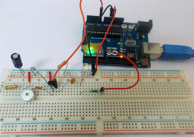
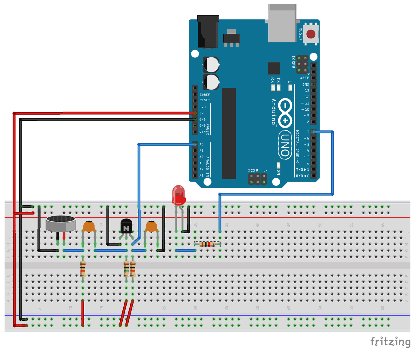
The circuit diagram of the clapper circuit is shown in below figure:
Clap Switch using Arduino
ARDUINOIn this project we are going to make Clapper circuitusing the concept of ADC (Analog to Digital Conversion) in ARDUINO UNO. We are going to use a MIC and Uno to sense the sound and trigger a response. This Clap ON Clap OFF switch basically turns ON or OFF the device, by using the clap sound, as switch. We have previously built Clap switch andClap ON Clap OFF switch, using 555 Timer IC.
On clapping there will be a peak signal at the MIC which is much higher than normal, this signal is fed to the amplifier, though a High Pass Filter. This amplified voltage signal is fed to ADC, which converts this high voltage into a number. So there will be a peak in the ADC reading of the UNO. On this peak detection we will toggle an LED on the board, on each clap. This project has been explained in detail below.
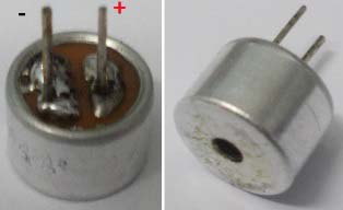
MIC or Microphone is a sound sensing transducer, which basically converts sound energy into electrical energy, so with this sensor we have sound as changing voltage. We usually record or sense sound through this device. This transducer is used in all mobile phones and laptops. A typical MIC looks like,
Determining the polarity of Condenser Mic:
MIC has two terminals one is positive and another is negative. Mic polarity can be found using a Multi-Meter. Take the positive probe of Multi-Meter (put the meter in DIODE TESTING mode) and connect it to one terminal of MIC and the negative probe to the other terminal of MIC. If you get the readings on the screen then the terminal of positive (MIC) is at negative terminal of Multi-Meter. Or you can simply find the terminals by looking at it, the negative terminal has two or three soldering lines, connected to the metal case of the mic. This connectivity, from negative terminal to its metal case can also be tested using continuity tester, to find out the negative terminal.
Components Required:
Hardware:
ARDUINO UNO, power supply (5v), a condenser mic (explained above)
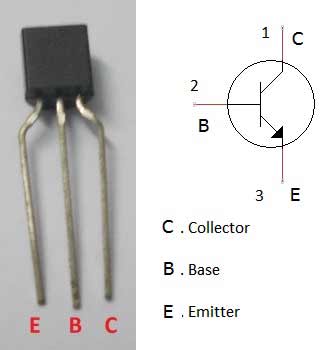
2N3904 NPN transistor,
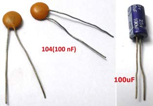
100nF capacitors (2 pieces), one 100uF capacitor,
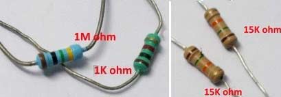
1K Ω resistor, 1MΩ resistor, 15KΩ resistor (2 pieces), one LED,
And Breadboard & Connecting wires.
Software: Arduino IDE - Arduino nightly.
Circuit Diagram and Working Explanation:
The circuit diagram of the clapper circuit is shown in below figure:
We have divided the working into four parts, that is: Filtration, Amplification, Analog-digital conversion and programming to toggle the LED
Whenever there is sound, the MIC picks it up and converts it into voltage, linear to the magnitude of sound. So for a higher sound we have higher value and for lower sound we have lower value. This value is first fed to the High Pass Filter for filtration. Then this filtered value is fed to the transistor foramplification and transistor provides the amplified output at the collector. This collector signal is fed to the ADC0 channel of the UNO, for Analog to Digital conversion. And lastly Arduino is programmed to toggle the LED, connected at PIN 7 of PORTD, each time ADC channel A0 goes beyond a particular level.
1. Filtration:
First of all we will talk briefly about R-C High Pass Filter, which has been used to filter out the noises. It’s easy to design and consists of a single resistor and single capacitor. For this circuit we don’t need much detail, so we will keep it simple. A high pass filter allows signals of high frequency pass from input to output, in other words the input signal appears at the output if the frequency of signal is higher than the filter prescribed frequency. For now, we need not to worry about these values because here we are not designing an audio amplifier. A high pass filter is shown in the circuit.
After this filter, voltage signal is fed to the transistor for amplification.
2. Amplification:
The voltage of MIC is very low and cannot be fed to UNO for ADC (Analog to Digital Conversion), so for this we design a simple amplifier using a transistor. Here we have designed a single transistor amplifier for amplifying the MIC voltages. This amplified voltage signal is further fed to the ADC0 channel of Arduino.
3. Analog to Digital Conversion:
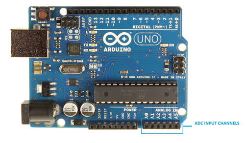
ARDUINO has 6 ADC channels. Among those, any one or all of them can be used as inputs for analog voltage. The UNO ADC is of 10 bit resolution (so the integer values from (0-(2^10) 1023)).This means that it will map input voltages between 0 and 5 volts into integer values between 0 and 1023. So for every (5/1024= 4.9mV) per unit.
Now, for the UNO to convert analog signal into digital signal, we need to Use ADC Channel of ARDUINO UNO, with the help of below functions:
1.    analogRead(pin);
2.    analogReference();
UNO ADC channels have a default reference value of 5V. This means we can give a maximum input voltage of 5V for ADC conversion at any input channel. Since some sensors provide voltages from 0-2.5V, so with a 5V reference, we get lesser accuracy, so we have an instruction that enables us to change this reference value. So for changing the reference value we have “analogReference();”
In our circuit, we have left this reference voltage to the default, so we can read value from ADC channel 0, by directly calling function “analogRead(pin);”, here “pin” represents pin where we connected the analog signal, in this case it would be “A0”. The value from ADC can be taken into an integer as “int sensorValue = analogRead(A0); ”, by this instruction the value from ADC gets stored in the integer “sensorValue”. Now, we have the transistor value in digital form, in the memory of UNO.
4. Program Arduino to Toggle the LED on each Clap:
Under normal instances, the MIC provides normal signals and so we have normal digital values in the UNO, but on clapping there a peak provided by the MIC, with this we have a peak digital value in the UNO, we can program the UNO to toggle an LED ON and OFF whenever there is a peak. So on first clap the LED turns ON and stays ON. On second clap the LED turns OFF and stays OFF until the next clap. With this we have the clapper circuit. Check the program Code below.
const int analogInPin = A0; // Analog input pin 0
int sensorValue = 0;
void setup()
{
DDRD = 0xFF;
}
void loop()
{
sensorValue = analogRead(analogInPin); //read ADC value on channel 0
if(sensorValue>60)
{
PORTD ^=(1<<7); //If there is a peak toggle the LED on and OFF on pin7.
delay(250);
}
}


Comments